AI Image Sensor Calibration
Table of Contents:
- 1. Overview
- 2. Calibrate Digits Readings
- 3. Get Sensor Data.
1. Overview
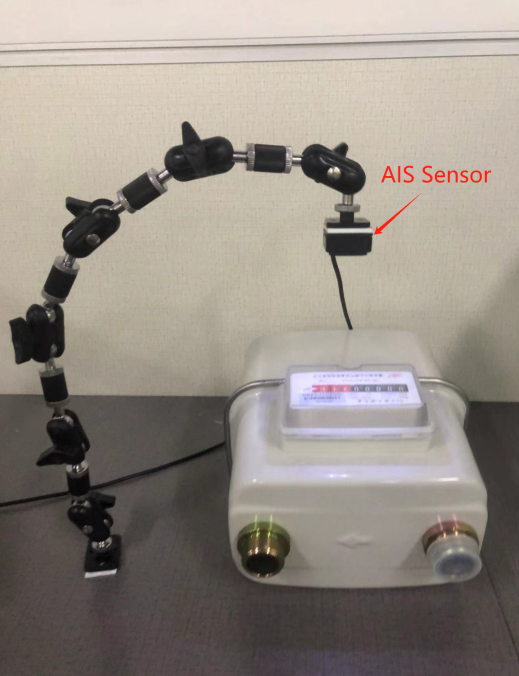
AIS is a video photo recognition sensor, the sensor can be used in electricity meters, gas meters, water meters, pressure gauges and other types of meters. Accurately identify the number of the current dial or upload the picture of the current dial for comparison, which can replace people to go to the door to read the meter, and is more accurate and energy-saving than the meter. The first thing to do is to fix the AIS sensor, the end direction needs to be aligned with the object that needs to be identified, you can check whether the object all appears in the lens range through the upper computer, and then calibrate, Chapter 2 will explain the calibration method of different tables.
2. Calibrate Digits Readings
2.1 Calibrate a Water Meter
2.1.1 Introduce
This water meter is designed in accordance with the Chinese standard for drinking cold water meters and hot water meters, GB/T 778.1-2007. It features five dial numbers for measurement accuracy.
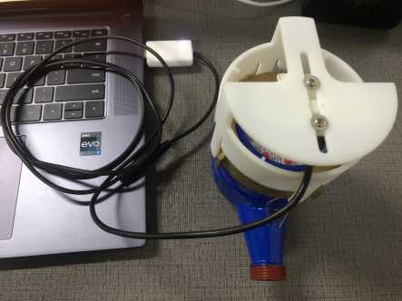
2.1.2 Fix Sensor to a Water Meter
The assembly necessitates the use of two screws, two spacers, and this specific device.
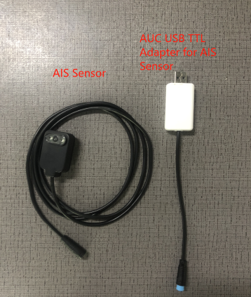
Additionally, there are AIS Sensors available along with AUC USB TTL adapters for AIS Sensors.
The fixture below is just a demo, user might adjust it with their water meter. Here is the STEP file for the fixture as below: Water Meter Fixture Demo.
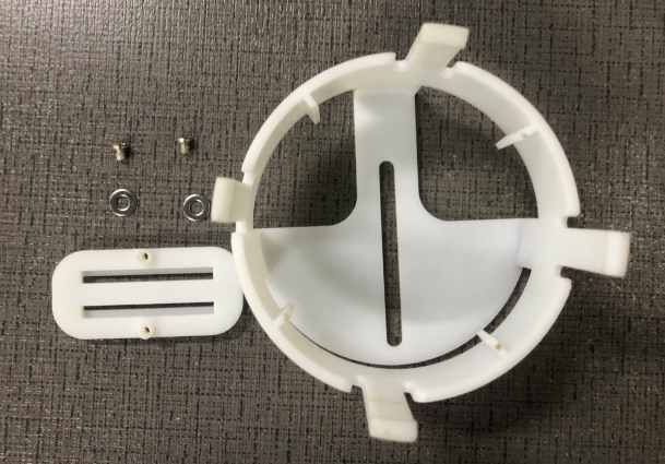
The procedure is as follows:
1. Secure back of the AIS sensor onto the small board and adjust its position according to your requirements. You may use two additional screws for fixation or utilize 3M double-sided adhesive for attachment.
2. Proceed by fastening the device using the previously prepared screws and gaskets.
3. Finally, nestle the device onto your water meter, ensuring that it can be adjusted to meet your specific needs while guaranteeing that the camera is directed towards the digital wheel face.
 .
.
The AI Sensors and AUC USB TTL Adapter for AIS Sensors are connected and then connected to the PC.
2.1.3 Calibration
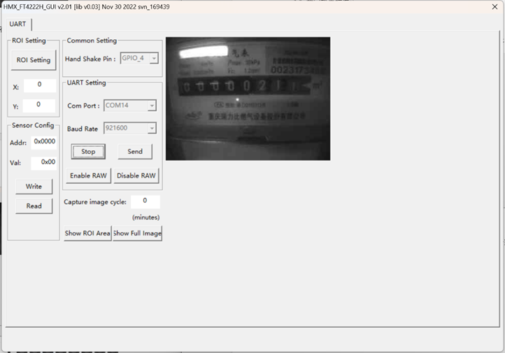
Launch HMX_FT4222H_GUI.exe. Please ensure that the firmware upgrade software ota.exe is closed before opening HMX_FT4222H_GUI.exe.
Choose the largest number of serial port, for example, here shows 13 and 14, then choose 14.
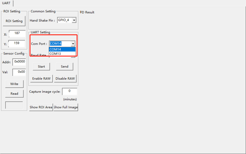
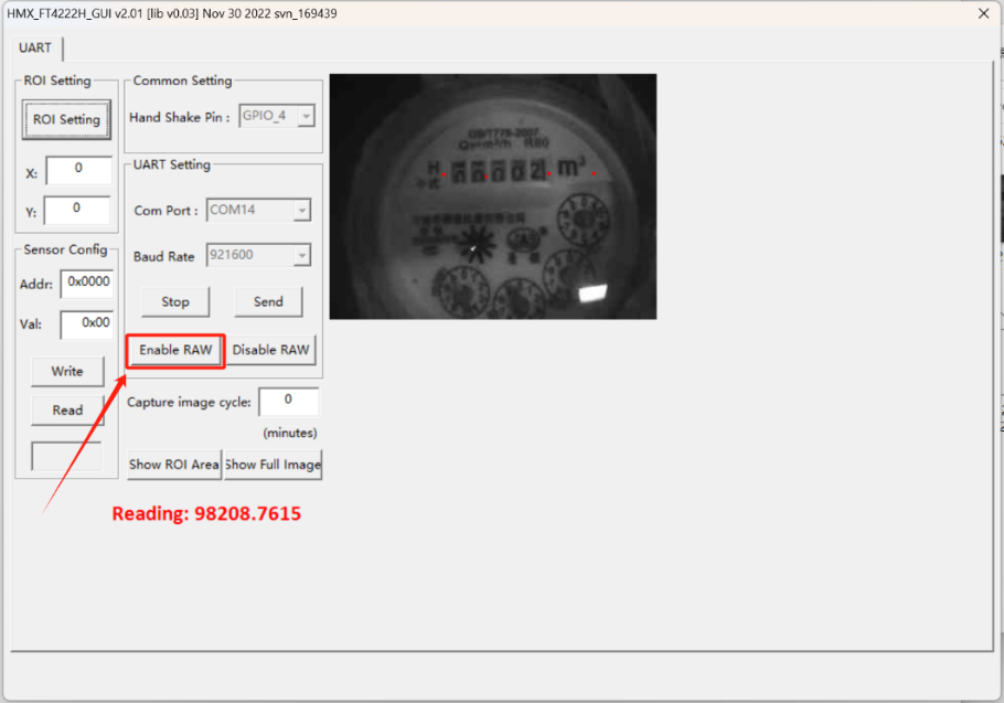
Next, select a Baud rate of 921600 and click on "start". Then, click on "show full image" to display the camera screen.
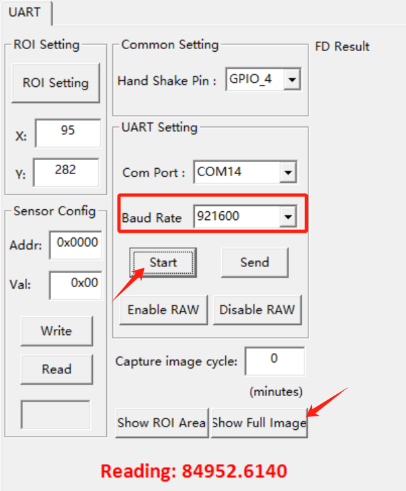

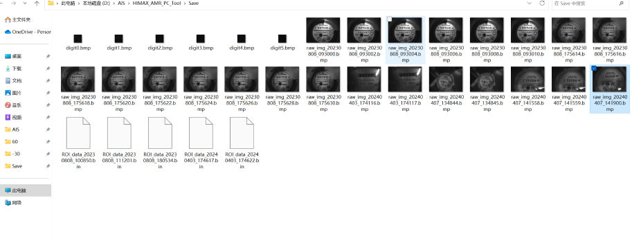
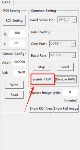
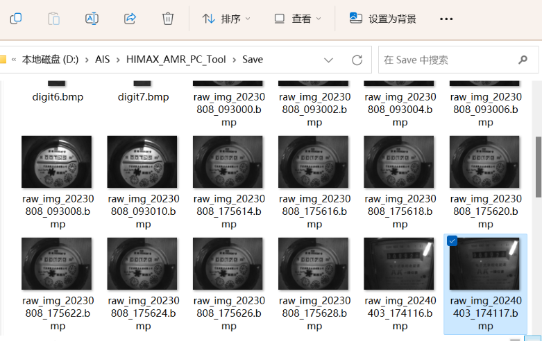
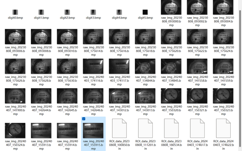
Click "enable Raw" and save the BMP image in the "Save" folder. This step is necessary to obtain the coordinate points of the watch face.
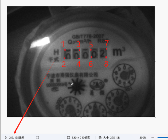
This water meter has only five fields, and the coordinates of the digital roulette wheel are shown in the figure.
If your device's digital scroll wheel dial does not match these five fields, you can try the other field dial coordinate dot plots in 2.4.
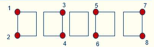
The computer's drawing tool can be used to open the latest bmp image and get the coordinates of the digital wheel dial, as shown below. Based on the format of the digital wheel dial, we can obtain each coordinate point of the current use dial. The (x,y) coordinate on the image is located at the bottom left corner.
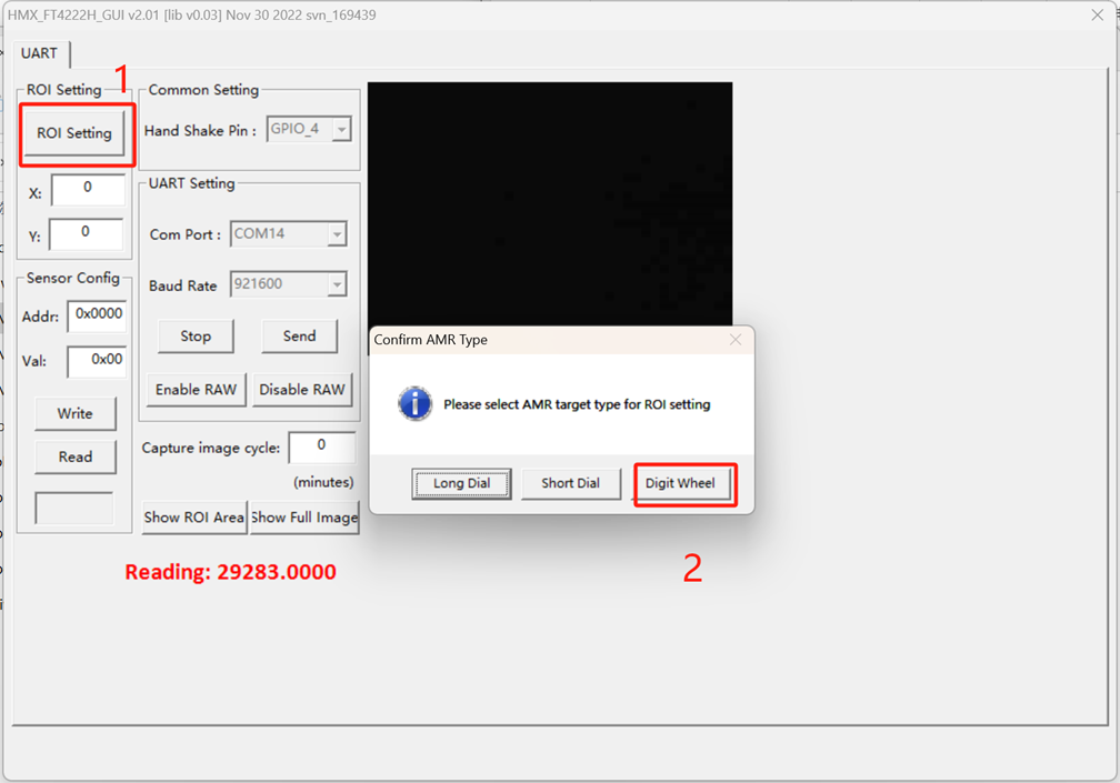
Click the "ROI setting" button in "HIMAX_AMR_PC_Tool" and three options will pop up
The "Long dial" option is the long hand dial.
The "Short dial" option is the short pointer and digital wheel dial.
The "Digit wheel" option is the digital wheel dial.
Now we are calibrating the digital wheel face of the water meter. Here we select "digit wheel".
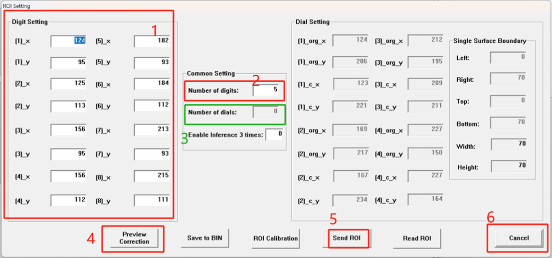
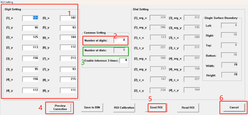
1:Fill in the coordinates you just got; it's best to get a coordinate and fill in a coordinate.
2: Fill in the number of number wheel on their dial,fi;
3: Select the number of short Pointers (currently we don't use short Pointers, the "digit wheelu" option defaults to 0);
4: Preview whether the setting of their coordinates is accurate;
5: Click to write all configuration to AIS;
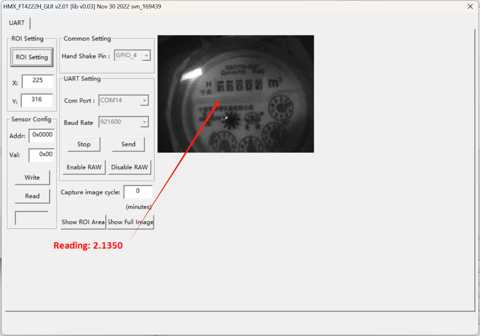
6: Click the exit configuration interface, at this time, there will be a readout. If the Reading of "reading" is consistent with the watch face, the calibration is successful. The AIS cannot move thereafter to avoid misreading.
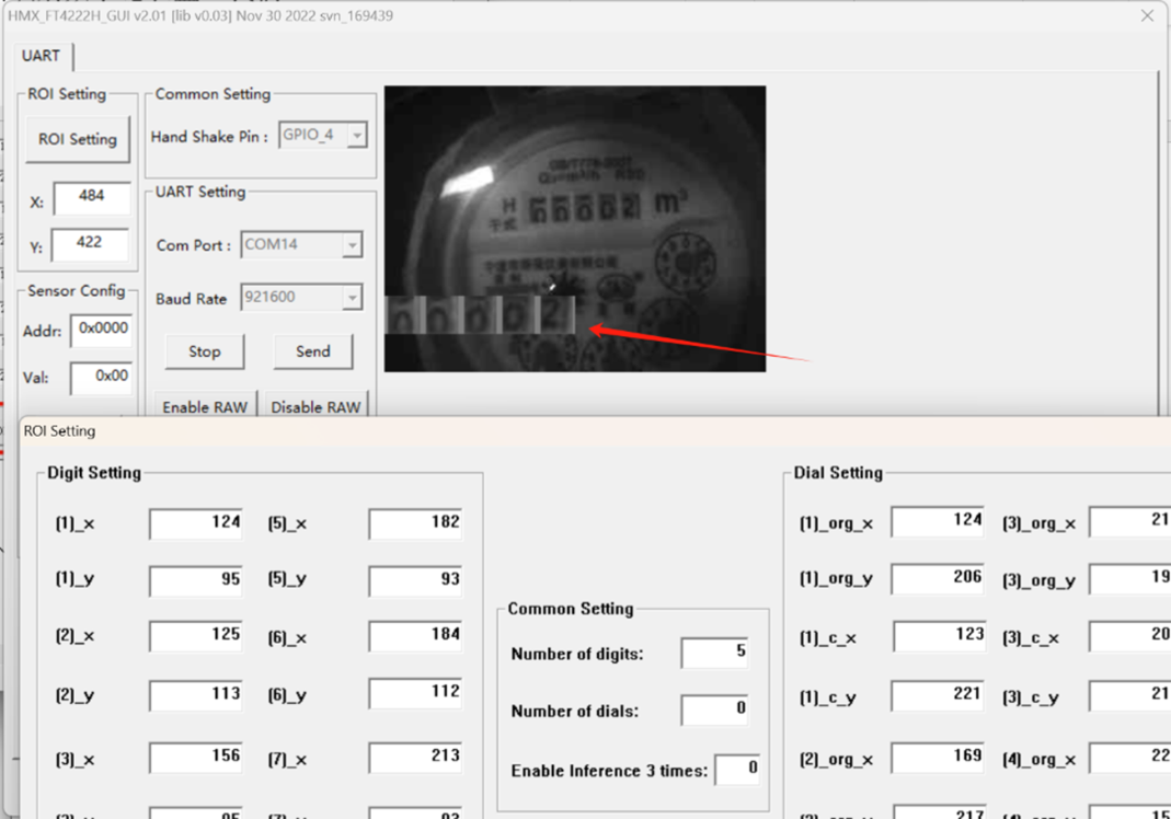
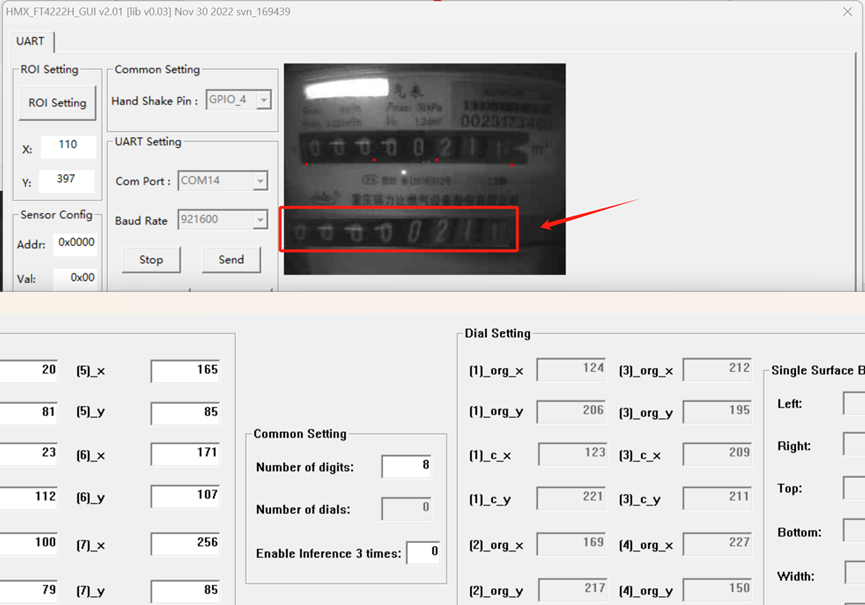
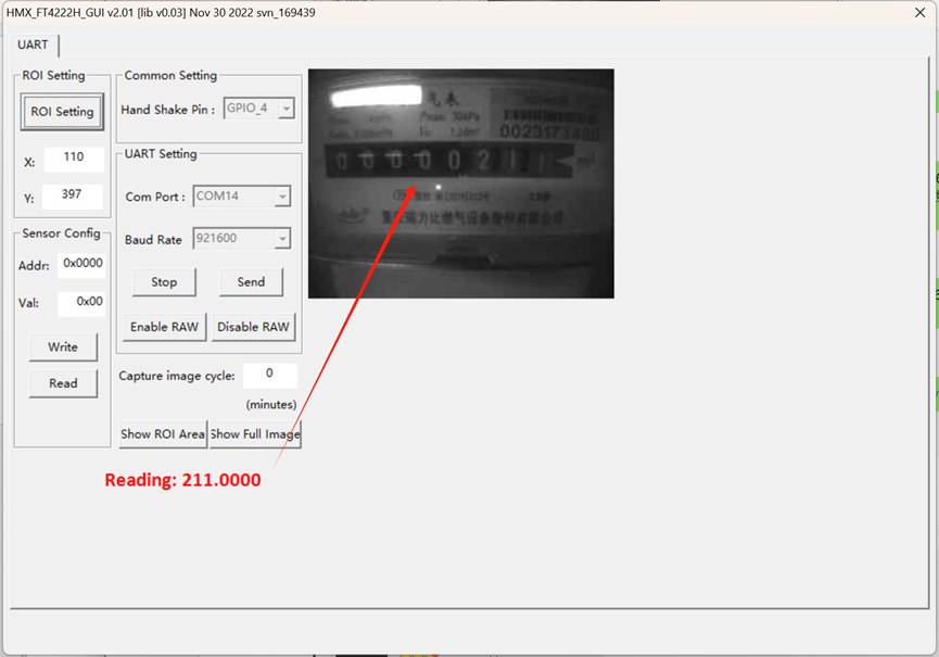
The effect can be previewed by clicking the "Preview correction" button as shown below.
![]()
After the calibration process is completed, it can be observed that the obtained reading aligns consistently with the numerical value displayed on the digital wheel dial.
2.2 Calibration Power Meter
2.2.1 Introduce
This power meter is designed in accordance with the Chinese standard for Electricity metering equipment, GB/T 17215.321-2008. It features six dial numbers for measurement accuracy.
2.2.2 Fix Sensor to a Power Meter
You can utilize a couple of pea clips or other suitable fixtures to securely fasten the AIS sensor and ensure precise alignment of the camera with the digital watch wheel.
2.2.3 Calibration
Perform a power reset on the EVB board, making sure to close the ota.exe program before opening HMX_FT4222H_GUI.exe.
Choose the largest number of serial port, for example, here shows 13 and 14, then choose 14.
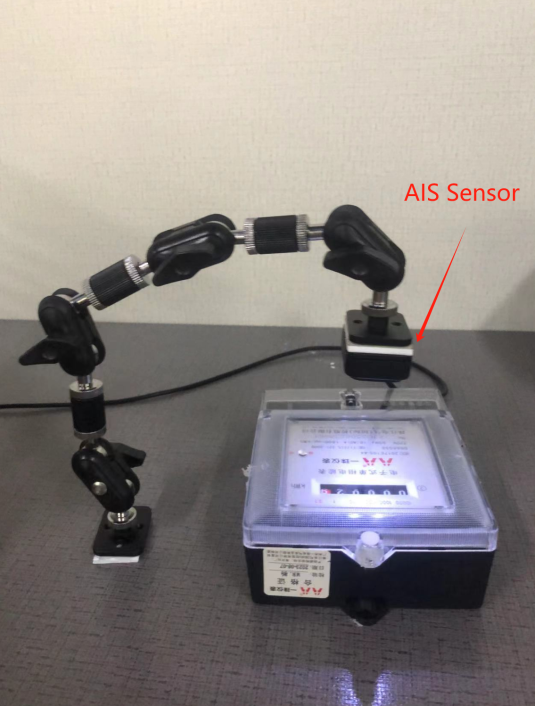
Next, select a Baud rate of 921600 and click on "start". Then, click on "show full image" to display the camera screen.
Click "enable Raw" and save the BMP image in the "Save" folder. This step is necessary to obtain the coordinate points of the watch face.
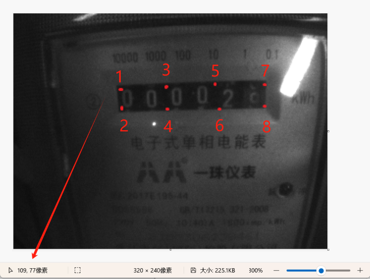
This power meter has only six fields, and the coordinates of the digital roulette wheel are shown in the figure.
If your device's digital scroll wheel dial does not match these six fields, you can try the other field dial coordinate dot plots in 2.4.

The computer's drawing tool can be used to open the latest bmp image and get the coordinates of the digital wheel dial, as shown below. Based on the format of the digital wheel dial, we can obtain each coordinate point of the current use dial. The (x,y) coordinate on the image is located at the bottom left corner.
Click the "ROI setting" button in "HIMAX_AMR_PC_Tool" and three options will pop up
The "Long dial" option is the long hand dial.
The "Short dial" option is the short pointer and digital wheel dial.
The "Digit wheel" option is the digital wheel dial.
Now we are calibrating the digital wheel face of the power meter. Here we select "digit wheel".
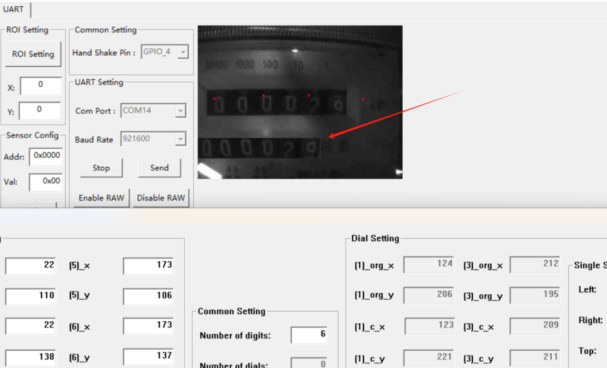
1: Fill in the coordinates you just got; it's best to get a coordinate and fill in a coordinate.
2: Fill in the number of number wheel on their dial,six;
3: Select the number of short Pointers (currently we don't use short Pointers, the "digit wheelu" option defaults to 0);
4: Preview whether the setting of their coordinates is accurate;
5: Click to write all configuration to AIS;
6: Click the exit configuration interface, at this time, there will be a readout. If the Reading of "reading" is consistent with the watch face, the calibration is successful. The AIS cannot move thereafter to avoid misreading.

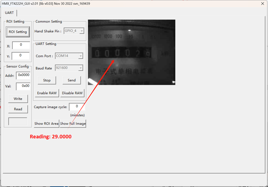
The effect can be previewed by clicking the "Preview correction" button as shown below.
After the calibration process is completed, it can be observed that the obtained reading aligns consistently with the numerical value displayed on the digital wheel dial.
2.3 Calibration Gas Meter
2.3.1 Introduce
This gas meter uses G2.5 membrane gas meter. It features eight dial numbers for measurement accuracy.
2.3.2 Fix Sensor to a Gas Meter
You can utilize a couple of pea clips or other suitable fixtures to securely fasten the AIS sensor and ensure precise alignment of the camera with the digital watch wheel.
2.3.3 Calibration
Perform a power reset on the EVB board, making sure to close the ota.exe program before opening HMX_FT4222H_GUI.exe.
Choose the largest number of serial port, for example, here shows 13 and 14, then choose 14.
Next, select a Baud rate of 921600 and click on "start". Then, click on "show full image" to display the camera screen.
Click "enable Raw" and save the BMP image in the "Save" folder. This step is necessary to obtain the coordinate points of the watch face.
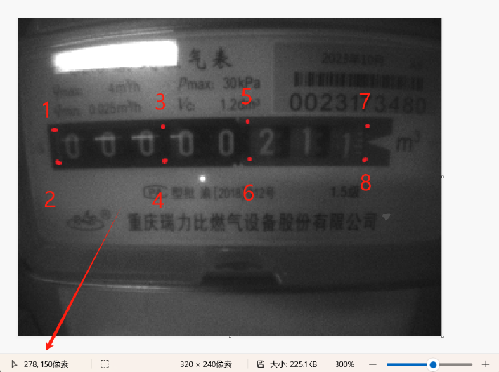
This gas meter has eight fields, and the coordinates of the digital roulette wheel are shown in the figure.
If your device's digital scroll wheel dial does not match these eight fields, you can try the other field dial coordinate dot plots in 2.4.

The computer's drawing tool can be used to open the latest bmp image and get the coordinates of the digital wheel dial, as shown below. Based on the format of the digital wheel dial, we can obtain each coordinate point of the current use dial. The (x,y) coordinate on the image is located at the bottom left corner.
Click the "ROI setting" button in "HIMAX_AMR_PC_Tool" and three options will pop up
The "Long dial" option is the long hand dial.
The "Short dial" option is the short pointer and digital wheel dial.
The "Digit wheel" option is the digital wheel dial.
Now we are calibrating the digital wheel face of the gas meter. Here we select "digit wheel".
1: Fill in the coordinates you just got; it's best to get a coordinate and fill in a coordinate.
2: Fill in the number of number wheel on their dial,eight;
3: Select the number of short Pointers (currently we don't use short Pointers, the "digit wheelu" option defaults to 0);
4: Preview whether the setting of their coordinates is accurate;
5: Click to write all configuration to AIS;
6: Click the exit configuration interface, at this time, there will be a readout. If the Reading of "reading" is consistent with the watch face, the calibration is successful. The AIS cannot move thereafter to avoid misreading.
The effect can be previewed by clicking the "Preview correction" button as shown below.
After the calibration process is completed, it can be observed that the obtained reading aligns consistently with the numerical value displayed on the digital wheel dial.
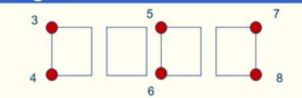
2.4 Digital wheel dial take point coordinate diagram
4 numbers:
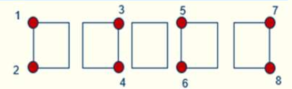
5 numbers:
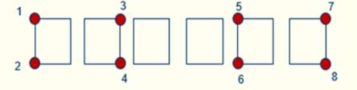
6 numbers:
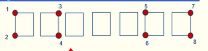
7 numbers:
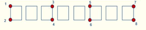
8 numbers:
3. Get Sensor Data.
3.1 Get Digital Reading After Calibration
This section shows an example for how to join the TheThingsNetwork LoRaWAN IoT server. Usages with other LoRaWAN IoT servers are of similar procedure.
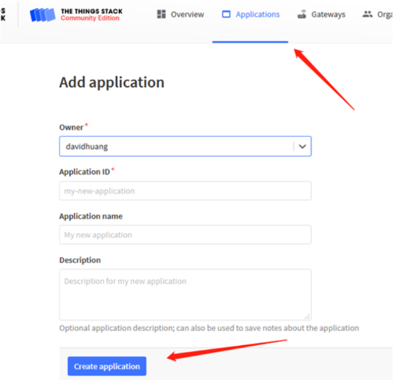
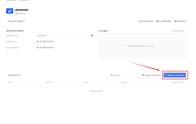
Assume the DLOS8 is already set to connect to TTN V3 network . We need to add the AIS Sensor device in TTN V3 portal.
Step 1: Create a device in TTN V3 with the OTAA keys from AIS Sensor.
Each AIS Sensor is shipped with a sticker with the default DEV EUI as below:
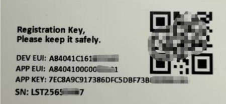
Enter these keys in the LoRaWAN Server portal. Below is TTN V3 screen shot:
Add APP EUI in the application.
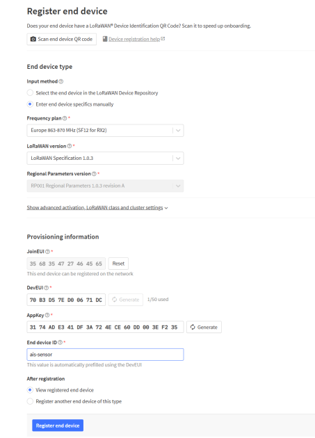
choose to create the device manually.
Add APP KEY and DEV EUI
Default mode OTAA
Step 2: Use ACT button to activate LHT52 and it will auto join to the TTN V3 network. After join success, it will start to upload sensor data to TTN V3 and user can see in the panel.
3.1.1 Uplink Payload (Fport=5)
The uplink payload includes totally 14 bytes. Uplink packets use FPORT=5 and every 20 minutes send one uplink by default.
| Size(bytes) | 2 | 4 | 4 | 4 |
|---|---|---|---|---|
| Value | BAT | sysTimeCurrent | Integer | Decimal |
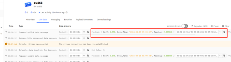
Payload Example(FPort=5):0D 32 66 29 AF E0 00 00 00 02 00 05 E3 B0
3.1.2 BAT- Battery information
These two bytes of BAT include the battery state and the actual voltage.
Ex:0x0B32 = 3378mV
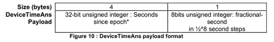
3.1.3 sysTimeCurrent
These four bytes contain the year, month, day, hour, minute, and second of the time.
AI Sensor use Unix TimeStamp format based on
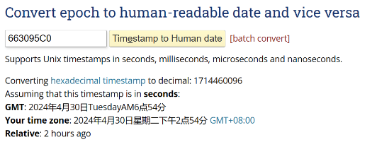
Users can get this time from the link: https://www.epochconverter.com/ :
Below is the converter example
Ex:6629AFE0=2024-04-25 01:20:32
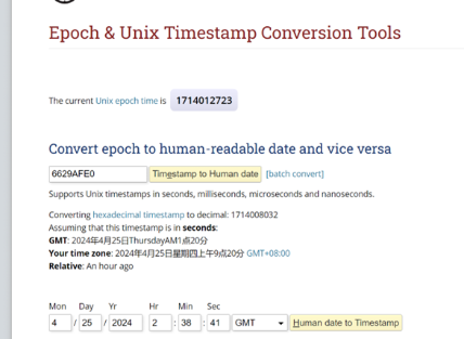
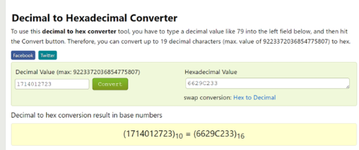
So, we can use AT+TIMESTAMP=1714012723 or downlink 6629C233 to set the current time 2024 – April -- 25 Thursday 02:38:41
3.1.4 Integer
These four bytes display the integers in the digital wheel face
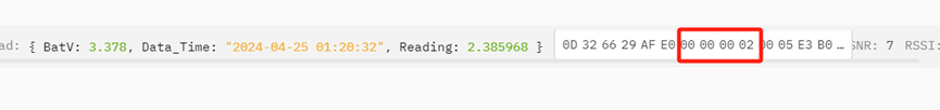
Read table integer:0x00000002=2
3.1.5 Decimal
These four bytes display decimals on the digital wheel.

Read table decimals:0x005E3B0/1000000= 0.385968
3.2 Get Image and show in PC
To get the AIS current image on the PC, you can issue commands through TTN or connect AIS to your PC with TTL to send commands through the serial port to obtain relevant data packets.
3.2.1 The image date are obtained by TTN
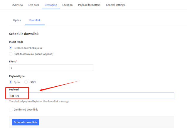
Make sure that node ACK is on: AT+PNACKMD=1 or 34 01
Then send the graph instruction 0B 01.
The next time the AIS Sensor device runs at the set time, it will start collecting image data.
The uplink payload includes totally 208 bytes. Uplink packets use FPORT=3
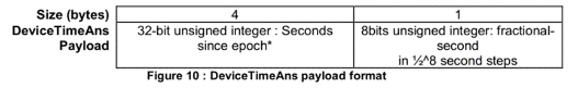
| Size(bytes) | 4 | 2 | 1 | 1 | 200 |
|---|---|---|---|---|---|
| Value | sysTimeCurrent | BAT | total_packages | subcontracting_count | Image_date |
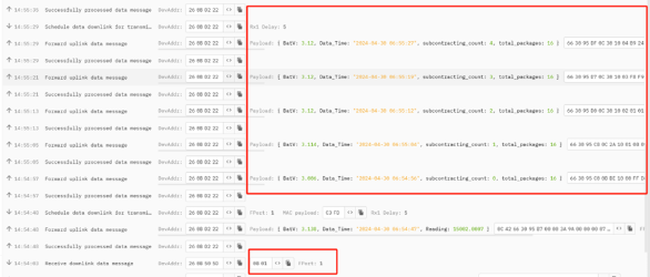
Example of the first payload(FPort=3):663095C00BBE1000FFD8FFE000104A46494600010101004800480000FFDB0043001B12141714111B1716171E1C1B2028422B28252528513A3D3042605565645F555D5B6A7899816A7190735B5D85B586909EA3ABADAB6780BCC9BAA6C799A8ABA4FFDB0043011C1E1E2823284E2B2B4EA46E5D6EA4A4A4A4A4A4A4A4A4A4A4A4A4A4A4A4A4A4A4A4A4A4A4A4A4A4A4A4A4A4A4A4A4A4A4A4A4A4A4A4A4A4A4A4A4A4A4A4A4A4FFC0000B0800F0014001012200FFC4001F00000105010101010101000000000000000001020304050607
3.2.1.1sysTimeCurrent
These four bytes contain the year, month, day, hour, minute, and second of the time.
AI Sensor use Unix TimeStamp format based on.
Users can get this time from the link: https://www.epochconverter.com/ :
Below is the converter example
EX: 663095C0=2024-04-30 06:54:57.
3.2.1.2 BAT- Battery information
These two bytes of BAT include the battery state and the actual voltage.

Ex:0X0BBE= 3006 mv
3.2.1.3 total_packages
This byte represents the total number of packets for the image fetched this time.
![]()
3.2.1.4 subcontracting_count
This byte represents the data number of the image packet retrieved
![]()
3.2.1.5 Image_date
Apart from the eight bytes mentioned above, the next 200 bytes are all image data.
Example the first packet:663095C00BBE1000FFD8FFE000104A46494600010101004800480000FFDB0043001B12141714111B1716171E1C1B2028422B28252528513A3D3042605565645F555D5B6A7899816A7190735B5D85B586909EA3ABADAB6780BCC9BAA6C799A8ABA4FFDB0043011C1E1E2823284E2B2B4EA46E5D6EA4A4A4A4A4A4A4A4A4A4A4A4A4A4A4A4A4A4A4A4A4A4A4A4A4A4A4A4A4A4A4A4A4A4A4A4A4A4A4A4A4A4A4A4A4A4A4A4A4A4FFC0000B0800F0014001012200FFC4001F00000105010101010101000000000000000001020304050607
Image_date=FFD8FFE000104A46494600010101004800480000FFDB0043001B12141714111B1716171E1C1B2028422B28252528513A3D3042605565645F555D5B6A7899816A7190735B5D85B586909EA3ABADAB6780BCC9BAA6C799A8ABA4FFDB0043011C1E1E2823284E2B2B4EA46E5D6EA4A4A4A4A4A4A4A4A4A4A4A4A4A4A4A4A4A4A4A4A4A4A4A4A4A4A4A4A4A4A4A4A4A4A4A4A4A4A4A4A4A4A4A4A4A4A4A4A4A4FFC0000B0800F0014001012200FFC4001F00000105010101010101000000000000000001020304050607
3.2.1.6 Combined image
Once all the data has been uploaded to the TTN platform, the subsequent step involves concatenating each packet in sequential order and saving it into a new TXT file. It is important to note that the first 8 bytes of each packet should be removed before concatenation.
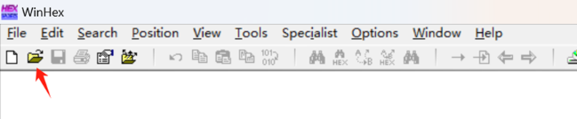
When you combine all the packets, you need to convert the data inside to binary. Here the conversion is demonstrated using the WinHex software.
Open WinHex to open the combined image data file.
Click on the edit option to choose and convert.
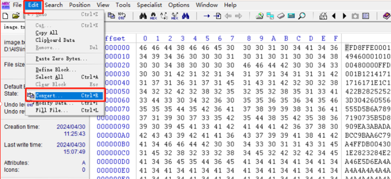
Choose the Hex ASCII->Binary option and then click OK.
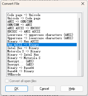
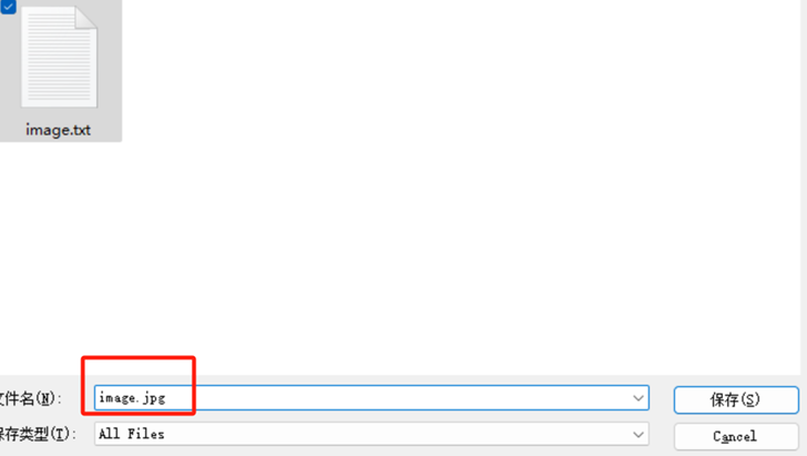
After the conversion is finished, click on "File" and choose "Save As".
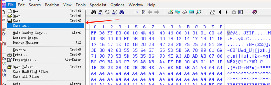
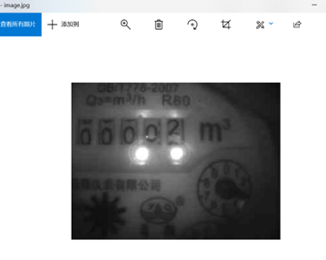
Save as a.jpg file and click OK to generate a JPG file.
Open the saved JPG file to display the image transmitted by the AIS Sensor through the serial port.
3.2.2 The image date are obtained by serial port
Select the corresponding baud rate and serial port number through the serial port tool, select HEX display and HEX send, and continuously receive data from the AIS Sensor
In the serial port to send data C0 5A 00 00 00 00 04, and then send C0 5A 00 00 00 00 09, AIS Sensor will send a real-time image of the data packet, and then stop sending. Start with FFD8 and put it in TXT file
Then follow the instructions in 3.2.1.6 to get the image from AIS Sensor.