AIS01-LB -- LoRaWAN AI Image End Node User Manual
Table of Contents:
- 1. Introduction
- 2. Configure AIS01-LB to connect to LoRaWAN network
- 2.1 How it works
- 2.2 Quick guide to connect to LoRaWAN server (OTAA)
- 2.3 Uplink Payload
- 2.4 Payload Decoder file
- 2.5 Frequency Plans
- 3. Configure AIS01-LB
- 4. Battery & Power Consumption
- 5. OTA Firmware update
- 6. FAQ
- 7. Order Info
- 8. Packing Info
- 9. Support
1. Introduction
1.1 What is AIS01-LB
AIS01-LB is a LoRaWAN AI Image End Node. AIS01-LB has a camera and AI processor in the probe. It can take photo , analyze the photo to get digital reading and send the info to IoT server via LoRaWAN Network.
AIS01-LB is pre-trained to support image recognized of water meter, gas meter and power meter. It can be trained to support more image recognized for different application.
AIS01-LB can send the digital reading after recognized and it can also send the original photo via LoRaWAN as well.
AIS01-LB is fully compatible with LoRaWAN v1.0.3 protocol, it can work with standard LoRaWAN gateway.
1.2 Features
- LoRaWAN v1.0.3 Class A protocol.
- Low power consumption
- AI Image Sensor.
- Send image to IoT server
- Recognize digits from Image and send data to IoT server
- Trained for common reading for Water Meter, Gas Meter, Power Meter
- Frequency Bands: CN470/EU433/KR920/US915/EU868/AS923/AU915
- Support Interrupt uplink
- Support Bluetooth v5.1 and LoRaWAN remote configure
- Support wireless OTA update firmware
- AT Commands to change parameters
- Uplink on periodically
- Downlink to change configure
- 8500mAh Li/SOCl2 Battery
1.3 Specification
Common DC Characteristics:
- Supply Voltage: Built-in Battery , 2.5v ~ 3.6v
- Operating Temperature: -40 ~ 85°C
I/O Interface:
- Battery output (2.6v ~ 3.6v depends on battery)
- +5v controllable output
- 3 x Interrupt or Digital IN/OUT pins
- 3 x one-wire interfaces
- 1 x UART Interface
- 1 x I2C Interface
LoRa Spec:
- Frequency Range, Band 1 (HF): 862 ~ 1020 Mhz
- Max +22 dBm constant RF output vs.
- RX sensitivity: down to -139 dBm.
- Excellent blocking immunity
Battery:
- Li/SOCI2 un-chargeable battery
- Capacity: 8500mAh
- Self-Discharge: <1% / Year @ 25°C
- Max continuously current: 130mA
- Max boost current: 2A, 1 second
Power Consumption:
- Sleep Mode: 5uA @ 3.3v
- LoRa Transmit Mode: 125mA @ 20dBm, 82mA @ 14dBm
1.4 Sleep mode and working mode
Deep Sleep Mode: Sensor doesn't have any LoRaWAN activate. This mode is used for storage and shipping to save battery life.
Working Mode: In this mode, Sensor will work as LoRaWAN Sensor to Join LoRaWAN network and send out sensor data to server. Between each sampling/tx/rx periodically, sensor will be in IDLE mode), in IDLE mode, sensor has the same power consumption as Deep Sleep mode.
1.5 Button & LEDs
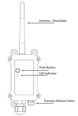
| Behavior on ACT | Function | Action |
|---|---|---|
| Pressing ACT between 1s < time < 3s | Send an uplink | If sensor is already Joined to LoRaWAN network, sensor will send an uplink packet, blue led will blink once. |
| Pressing ACT for more than 3s | Active Device | Green led will fast blink 5 times, device will enter OTA mode for 3 seconds. And then start to JOIN LoRaWAN network. |
| Fast press ACT 5 times. | Deactivate Device | Red led will solid on for 5 seconds. Means device is in Deep Sleep Mode. |
1.6 BLE connection
AIS01-LB supports BLE remote configure.
BLE can be used to configure the parameter of sensor or see the console output from sensor. BLE will be only activate on below case:
- Press button to send an uplink
- Press button to active device.
- Device Power on or reset.
If there is no activity connection on BLE in 60 seconds, sensor will shut down BLE module to enter low power mode.
1.7 Pin Definitions
AIS01-LB use the mother board which as below.

1.7.1 Jumper JP2
Power on Device when put this jumper.
1.7.2 BOOT MODE / SW1
1) ISP: upgrade mode, device won't have any signal in this mode. but ready for upgrade firmware. LED won't work. Firmware won't run.
2) Flash: work mode, device starts to work and send out console output for further debug
1.7.3 Reset Button
Press to reboot the device.
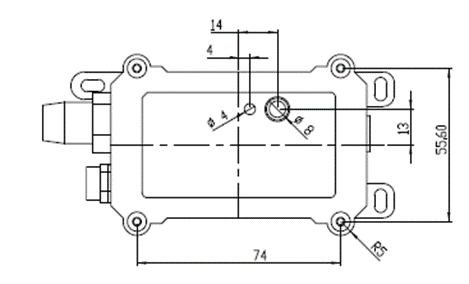
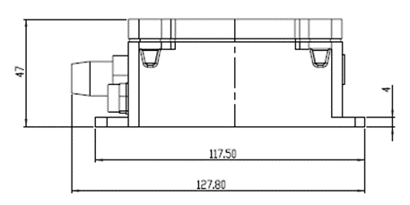
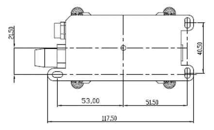
1.8 Mechanical
1.8.1 for LB version
2. Configure AIS01-LB to connect to LoRaWAN network
2.1 How it works
The AIS01-LB is configured as LoRaWAN OTAA Class A mode by default. It has OTAA keys to join LoRaWAN network. To connect a local LoRaWAN network, you need to input the OTAA keys in the LoRaWAN IoT server and press the button to activate the AIS01-LB. It will automatically join the network via OTAA and start to send the sensor value. The default uplink interval is 20 minutes.
2.2 Quick guide to connect to LoRaWAN server (OTAA)
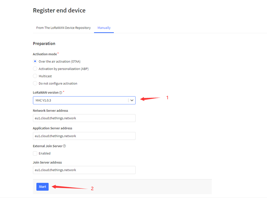
Following is an example for how to join the TTN v3 LoRaWAN Network. Below is the network structure; we use the LPS8v2 as a LoRaWAN gateway in this example.
The LPS8v2 is already set to connected to TTN network , so what we need to now is configure the TTN server.

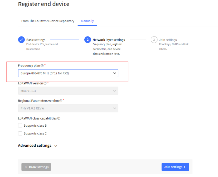
Step 1: Create a device in TTN with the OTAA keys from AIS01-LB.
Each AIS01-LB is shipped with a sticker with the default device EUI as below:
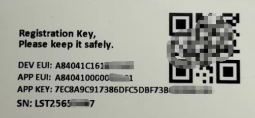
You can enter this key in the LoRaWAN Server portal. Below is TTN screen shot:
Register the device
Add APP EUI and DEV EUI
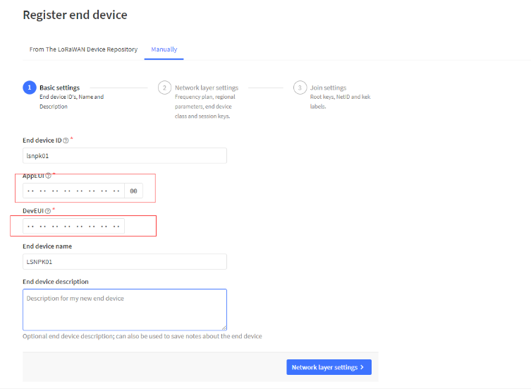
Add APP EUI in the application
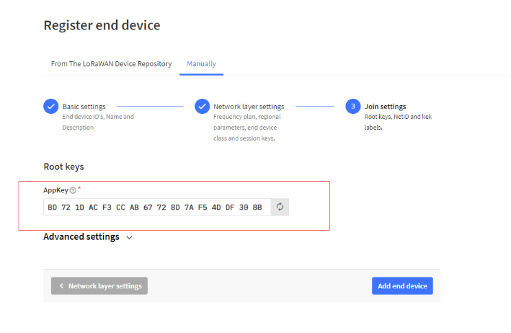
Add APP KEY
Step 2: Activate AIS01-LB
Press the button for 5 seconds to activate the AIS01-LB.
Green led will fast blink 5 times, device will enter OTA mode for 3 seconds. And then start to JOIN LoRaWAN network. Green led will solidly turn on for 5 seconds after joined in network.
After join success, it will start to upload messages to TTN and you can see the messages in the panel.
2.3 Uplink Payload
2.3.1 Device Status, FPORT=5
Users can use the downlink command(0x26 01) to ask AIS01-LB to send device configure detail, include device configure status. AIS01-LB will uplink a payload via FPort=5 to server.
The Payload format is as below.
| Device Status (FPORT=5) | |||||
| Size (bytes) | 1 | 2 | 1 | 1 | 2 |
| Value | Sensor Model | Firmware Version | Frequency Band | Sub-band | BAT |
Example parse in TTNv3
Sensor Model: For AIS01-LB, this value is 0x1C
Firmware Version: 0x0100, Means: v1.0.0 version
Frequency Band:
0x01: EU868
0x02: US915
0x03: IN865
0x04: AU915
0x05: KZ865
0x06: RU864
0x07: AS923
0x08: AS923-1
0x09: AS923-2
0x0a: AS923-3
0x0b: CN470
0x0c: EU433
0x0d: KR920
0x0e: MA869
Sub-Band:
AU915 and US915:value 0x00 ~ 0x08
CN470: value 0x0B ~ 0x0C
Other Bands: Always 0x00
Battery Info:
Check the battery voltage.
Ex1: 0x0B45 = 2885mV
Ex2: 0x0B49 = 2889mV
2.3.2 Timing upload the identified number and time FPORT=2
The uplink payload includes totally 14 bytes. Uplink packets use FPORT=2 and every 20 minutes send one uplink by default.
| Size(bytes) | 2 | 4 | 4 | 4 |
|---|---|---|---|---|
| Value | BAT | SysTimeCurrent | Integer | Decimal |
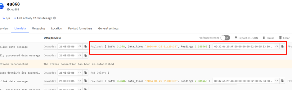
Payload Example(FPort=2):0D 32 66 29 AF E0 00 00 00 02 00 05 E3 B0
2.3.2.1 BAT- Battery information
These two bytes of BAT include the battery state and the actual voltage.

Ex:0x0B32 = 3378mV
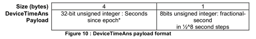
2.3.2.2 SysTimeCurrent
These four bytes contain the year, month, day, hour, minute, and second of the time.
![]()
AI Sensor use Unix TimeStamp format based on:
Users can get this time from the link: https://www.epochconverter.com/ :
Below is the converter example.
Ex:6629AFE0=2024-04-25 01:20:32
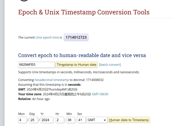
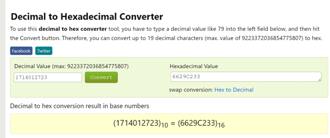
So, we can use AT+TIMESTAMP=1714012723 or downlink 6629C233 to set the current time 2024 – April -- 25 Thursday 02:38:41
2.3.2.3 Integer
These four bytes display the integers in the digital wheel face.
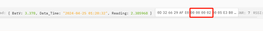
Read table integer:0x00000002=2
2.3.2.4 Decimal
These four bytes display decimals on the digital wheel.

Read table decimals:0x005E3B0/1000000= 0.385968
2.3.3 Image upload function FPORT=3
| Size(bytes) | 4 | 2 | 1 | 1 | 200 |
|---|---|---|---|---|---|
| Value | SysTimeCurrent | BAT | total_packages | subcontracting_count | Image_date |
Send the graph command 0B 01,AIS01 starts sending the picture data packet after sending the next data.
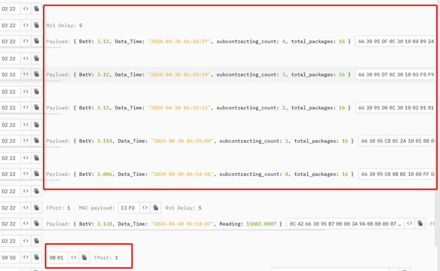
Example of the first payload(FPort=3):
663095C00BBE1000FFD8FFE000104A46494600010101004800480000FFDB0043001B12141714111B1716171E1C1B2028422B28252528513A3D3042605565645F555D5B6A7899816A7190735B5D85
B586909EA3ABADAB6780BCC9BAA6C799A8ABA4FFDB0043011C1E1E2823284E2B2B4EA46E5D6EA4A4A4A4A4A4A4A4A4A4A4A4A4A4A4A4A4A4A4A4A4A4A4A4A4A4A4A4A4A4A4A4A4A4A4A4
A4A4A4A4A4A4A4A4A4A4A4A4A4A4FFC0000B0800F0014001012200FFC4001F00000105010101010101000000000000000001020304050607
2.3.3.1 SysTimeCurrent
These four bytes contain the year, month, day, hour, minute, and second of the time.
AI Sensor use Unix TimeStamp format based on.

Users can get this time from the link: https://www.epochconverter.com/ :
Below is the converter example
EX: 663095C0=2024-04-30 06:54:57.

2.3.3.2 BAT- Battery information
These two bytes of BAT include the battery state and the actual voltage.

Ex:0X0BBE= 3006 mv
2.3.3.3 total_packages
This byte represents the total number of packets for the image fetched this time.

2.3.3.4 subcontracting_count
This byte represents the data number of the image packet retrieved.
![]()
2.3.3.5 Image_date
Apart from the eight bytes mentioned above, the next 200 bytes are all image data.
Example: Payload: 663095C00BBE1000FFD8FFE000104A46494600010101004800480000FFDB0043001B12141714111B1716171E1C1B2028422B28252528513A3D3042605565645F555D5B6A789981
6A7190735B5D85B586909EA3ABADAB6780BCC9BAA6C799A8ABA4FFDB0043011C1E1E2823284E2B2B4EA46E5D6EA4A4A4A4A4A4A4A4A4A4A4A4A4A4A4A4A4A4A4A4A4A4A4A4A4A4A4A4A4A
4A4A4A4A4A4A4A4A4A4A4A4A4A4A4A4A4A4A4A4A4FFC0000B0800F0014001012200FFC4001F00000105010101010101000000000000000001020304050607
Image_date=FFD8FFE000104A46494600010101004800480000FFDB0043001B12141714111B1716171E1C1B2028422B28252528513A3D3042605565645F555D5B6A7899816A7190735B5D85B58690
9EA3ABADAB6780BCC9BAA6C799A8ABA4FFDB0043011C1E1E2823284E2B2B4EA46E5D6EA4A4A4A4A4A4A4A4A4A4A4A4A4A4A4A4A4A4A4A4A4A4A4A4A4A4A4A4A4A4A4A4A4A4A4A4A4A4A4A
4A4A4A4A4A4A4A4A4A4A4FFC0000B0800F0014001012200FFC4001F00000105010101010101000000000000000001020304050607
2.3.4 Image upload function FPORT=4
| Size(bytes) | 2 | 4 | 4 | 4 | 4 | 4 | 4 | ...... |
|---|---|---|---|---|---|---|---|---|
| Value | BAT | SysTimeCurrent | Integer | Decimal | SysTimeCurrent | Integer | Decimal |
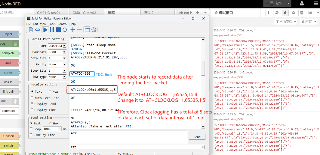
FPORT 4 is somewhat similar to FPORT 2 in that how many packets you will receive depends on your CLOCKLOG Settings.
For example:
The AT + CLOCKLOG = 1,65535,1,5
AT+TDC=30000
Five minutes after AIS01-LB is connected to the network, You will receive a payload containing a battery, five times and five meter readings corresponding to the time.
![]()
![]()
Example: Payload:
0A8C 663C66C6 02000000 3CAE0100 663C65D6 02000000 7A0F0200 663C6612 02000000 3CAE0100 663C664E 02000000 3CAE0100 663C668A 02000000 3CAE0100
2.3.4.1 BAT- Battery information
These two bytes of BAT include the battery state and the actual voltage.
Ex: 0x0A8C= 2700 mv
2.3.4.2 SysTimeCurrent
Because this is data from five different times being combined together, it needs to be distinguished.
Ex:
0x663C66C6E="2024-05-09 06:01:42",
0x663C65D6= "2024-05-09 05:57:42",
0x663C6612="2024-05-09 05:58:42",
0x663C664E="2024-05-09 05:59:42",
0x663C668A="2024-05-09 06:00:42"
2.3.4.3 Integer
The five data points of Integer are: 02 00 00 00
Notice that the packet order is reversed here.

Ex:0x02000000=0x00000002=2
2.3.4.4 Decimal
Notice that the packet order is reversed here.

Ex:
0x3CAE0100=0x0001AE3C=11014
0x7A0F0200=0x00020F7A=135034
0x3CAE0100=0x0001AE3C=11014
0x3CAE0100=0x0001AE3C=11014
0x3CAE0100=0x0001AE3C=11014
2.3.5 Datalog FPORT=6
After turning on the ACK function, AIS01-LB will store every piece of data. When AIS01-LB is unable to upload data to the platform at the set time due to network fluctuations at certain times, AIS01-LB will store the collected data into flash. When AIS01-LB joins the network, the data will be packaged and sent to the platform.
| Size(bytes) | 4 | 4 | 4 | 4 | 4 | 4 | ...... |
|---|---|---|---|---|---|---|---|
| Value | SysTimeCurrent | Integer | Decimal | SysTimeCurrent | Integer | Decimal |
FPORT 6 is somewhat similar to FPORT 4 with only two bytes less data about the battery.

Example of Device Status: 664809FC000000020006BF6F 66480A38000000020007A120
2.3.5.1 SysTimeCurrent
These four bytes contain the year, month, day, hour, minute, and second of the time.
AI Sensor use Unix TimeStamp format based on.
Users can get this time from the link: https://www.epochconverter.com/ :
0x66482503="2024-05-18 01:53:00"
0x6648253F="2024-05-18 01:54:00"
2.3.5.2 Integer
![]()
The two data points of Integer are: 00000002
Ex:0x02000000=0x00000002=2
2.3.5.3 Decimal
![]()
These four bytes display decimals on the digital wheel.
Read table decimals:0x0007A120/1000000= 0.5
2.3.6 Decode payload
While using TTN V3 network, you can add the payload format to decode the payload.
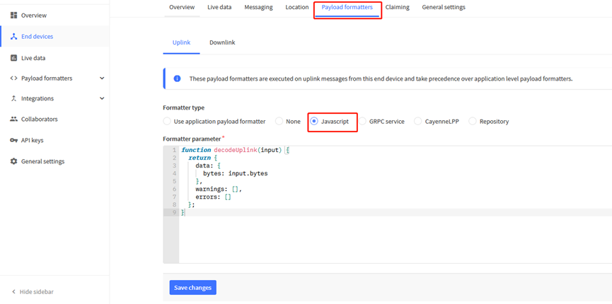
The payload decoder function for TTN V3 are here:
AIS01-LB TTN V3 Payload Decoder: https://github.com/dragino/dragino-end-node-decoder
2.4 Payload Decoder file
In TTN, use can add a custom payload so it shows friendly reading.
In the page Applications --> Payload Formats --> Custom --> decoder to add the decoder from: (To be added)
https://github.com/dragino/dragino-end-node-decoder/tree/main/SN50_v3-LB
2.5 Frequency Plans
The AIS01-LB uses OTAA mode and below frequency plans by default. Each frequency band use different firmware, user update the firmware to the corresponding band for their country.
http://wiki.dragino.com/xwiki/bin/view/Main/End%20Device%20Frequency%20Band/
3. Configure AIS01-LB
3.1 Configure Methods
AIS01-LB supports below configure method:
- AT Command via Bluetooth Connection (Recommended): BLE Configure Instruction.
- AT Command via UART Connection : See UART Connection.
- LoRaWAN Downlink. Instruction for different platforms: See IoT LoRaWAN Server section.
3.2 General Commands
These commands are to configure:
- General system settings like: uplink interval.
- LoRaWAN protocol & radio related command.
They are same for all Dragino Devices which support DLWS-005 LoRaWAN Stack. These commands can be found on the wiki:
http://wiki.dragino.com/xwiki/bin/view/Main/End%20Device%20AT%20Commands%20and%20Downlink%20Command/
3.3 Commands special design for AIS01-LB
These commands only valid for AIS01-LB, as below:
3.3.1 Set Transmit Interval Time
Feature: Change LoRaWAN End Node Transmit Interval.
AT Command: AT+TDC
| Command Example | Function | Response |
|---|---|---|
| AT+TDC=? | Show current transmit Interval | 30000 |
| AT+TDC=60000 | Set Transmit Interval | OK |
Downlink Command: 0x01
Format: Command Code (0x01) followed by 3 bytes time value.
If the downlink payload=0100003C, it means set the END Node's Transmit Interval to 0x00003C=60(S), while type code is 01.
- Example 1: Downlink Payload: 0100001E // Set Transmit Interval (TDC) = 30 seconds
- Example 2: Downlink Payload: 0100003C // Set Transmit Interval (TDC) = 60 seconds
3.3.2 Get Device Status
Send a LoRaWAN downlink to ask the device to send its status.
Downlink Payload: 0x26 01
Sensor will upload Device Status via FPORT=5. See payload section for detail.
3.3.3 Set Interrupt Mode
Feature, Set Interrupt mode for GPIO_EXIT.
AT Command: AT+INTMOD1,AT+INTMOD2
| Command Example | Function | Response |
|---|---|---|
| AT+INTMOD1=? | Show current interrupt mode | 0 |
| AT+INTMOD1=2 | Set Transmit Interval | OK |
| AT+INTMOD2=2 | Set Transmit Interval 0. (Disable Interrupt), 1. (Trigger by rising and falling edge) 2. (Trigger by falling edge) 3. (Trigger by rising edge) | OK |
Downlink Command: 0x06
Format: Command Code (0x06) followed by 3 bytes.
This means that the interrupt mode of the end node is set to 0x000003=3 (rising edge trigger), and the type code is 06.
- Example 1: Downlink Payload: 06000000 ---> AT+INTMOD1=0
- Example 2: Downlink Payload: 06000003 ---> AT+INTMOD1=3
- Example 3: Downlink Payload: 06000102 ---> AT+INTMOD2=2
3.3.4 Request the server to send an ACK
AT Command: AT+PNACKMD
| Command Example | Function | Response |
| AT+PNACKMD=1 | If the node uploads the ACK as confirm, it will request the server to send an ACK. If the server ack is not received, the node will upload the packets that have not received the ACK the next time it receives the ACK | 1 OK |
| AT+PNACKMD=0 | off request the server to send an ACK | 0 |
Downlink Command: 0x34
0X34 01 //Same As AT+PNACKMD=1
0x34 00 //Same As AT+PNACKMD=0
3.3.5 Print data entries base on page
Feature: Print the sector data from start page to stop page (max is 416 pages).
AT Command: AT+PDTA
| Command Example | Function |
AT+PDTA=1,3 | Stop Tx events when read sensor data 8031000 2024/5/18 01:29:00 3054 2.442223 8031010 2024/5/18 01:30:00 3048 2.442223 8031020 2024/5/18 01:31:00 3042 2.442223 8031030 2024/5/18 01:32:00 3036 2.442223 8031040 2024/5/18 01:33:00 3030 2.442223 8031050 2024/5/18 01:34:00 3024 2.442223 8031060 2024/5/18 01:35:00 3024 2.442223 8031070 2024/5/18 01:36:00 3018 2.442223 8031080 2024/5/18 01:37:00 3012 2.442223 8031090 2024/5/18 01:38:00 3000 2.442223 80310A0 2024/5/18 01:39:00 2994 2.442223 80310B0 2024/5/18 01:40:00 2988 2.442223 80310C0 2024/5/18 01:41:00 2982 2.442223 80310D0 2024/5/18 01:42:00 2976 2.442223 80310E0 2024/5/18 01:43:00 2970 2.442223 80310F0 2024/5/18 01:44:00 2964 2.442223 8031100 2024/5/18 01:45:00 2958 2.442223 8031110 2024/5/18 01:46:00 2952 2.442223 8031120 2024/5/18 01:47:00 2940 2.442223 8031130 2024/5/18 01:48:00 2940 2.442223 8031140 2024/5/18 01:49:00 2928 2.442223 8031150 2024/5/18 01:50:00 2922 2.442223 8031160 2024/5/18 01:51:00 2916 2.442223 8031170 2024/5/18 01:52:00 2904 2.442223 Start Tx events OK |
Downlink Command:
No downlink commands for feature
3.3.6 Clear Flash Record
Feature: Clear flash storage for data log feature.
AT Command: AT+CLRDTA
| Command Example | Function | Response |
| AT+CLRDTA | Clear date record | Stop Tx events,Please wait for the erase to complete Clear all stored sensor data... Start Tx events OK |
Downlink Command:
No downlink commands for feature
3.3.7 Clock logging
Sometimes when we deploy lots of end nodes in field. We want all sensors sample data at the same time, and upload these data together for analyze. In such case, we can use clock loging feature.
We can use this command to set the start time of data recording and the time interval to meet the requirements of the specific collection time of data.
- AT Command: AT+CLOCKLOG=a,b,c,d
a: 0: Disable Clock logging. 1: Enable Clock Logging
b: Specify First sampling start second: range (0 ~ 3599, 65535) // Note: If parameter b is set to 65535, the log period starts after the node accesses the network and sends packets.
c: Specify the sampling interval: range (0 ~ 255 minutes)
d:How many entries should be uplink on every TDC (max 32)
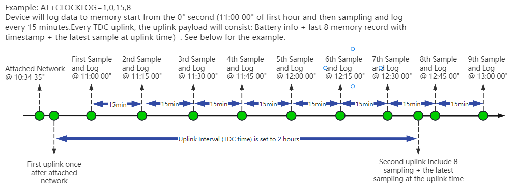
Example:
AT+CLOCKLOG=1,65535,1,5
After the node sends the first packet, data is recorded to the memory at intervals of 1 minute. For each TDC uplink, the uplink load will include: battery information + the last 5 memory records (payload + timestamp).
Note: Users need to synchronize the server time before configuring this command. If the server time is not synchronized before this command is configured, the command takes effect only after the node is reset.
4. Battery & Power Consumption
AIS01-LB use ER26500 + SPC1520 battery pack . See below link for detail information about the battery info and how to replace.
Battery Info & Power Consumption Analyze .
5. OTA Firmware update
User can change firmware AIS01-LB to:
- Change Frequency band/ region.
- Update with new features.
- Fix bugs.
Firmware and changelog can be downloaded from : Firmware download link
Methods to Update Firmware:
- (Recommanded way) OTA firmware update via wireless: http://wiki.dragino.com/xwiki/bin/view/Main/Firmware%20OTA%20Update%20for%20Sensors/
- Update through UART TTL interface: Instruction.
6. FAQ
6.1 Where can i find source code of AIS01-LB?(Uncertainty)
7. Order Info
Part Number: AIS01-LB-XX
XX: The default frequency band
- AS923: LoRaWAN AS923 band
- AU915: LoRaWAN AU915 band
- EU433: LoRaWAN EU433 band
- EU868: LoRaWAN EU868 band
- KR920: LoRaWAN KR920 band
- US915: LoRaWAN US915 band
- IN865: LoRaWAN IN865 band
- CN470: LoRaWAN CN470 band
8. Packing Info
Package Includes:
- AIS01-LB LoRaWAN AI Image End Node
Dimension and weight:
- Device Size: cm
- Device Weight: g
- Package Size / pcs : cm
- Weight / pcs : g
9. Support
- Support is provided Monday to Friday, from 09:00 to 18:00 GMT+8. Due to different timezones we cannot offer live support. However, your questions will be answered as soon as possible in the before-mentioned schedule.
- Provide as much information as possible regarding your enquiry (product models, accurately describe your problem and steps to replicate it etc) and send a mail to support@dragino.cc