PB01 -- LoRaWAN Button User Manual

Table of Contents:
- 1. Introduction
- 2. Operation Mode
- 3. Configure PB01 via AT command or LoRaWAN downlink
- 4. Battery & How to replace
- 5. Accessories
- 6. FAQ
- 7. Order Info
- 7. Packing Info
- 8. Support
- 9. Reference material
- 10. FCC Warning
1. Introduction
1.1 What is PB01 LoRaWAN Push Button
PB01 LoRaWAN Button is a LoRaWAN wireless device with one push button. Once user push the button, PB01 will transfer the signal to IoT server via Long Range LoRaWAN wireless protocol. PB01 also senses the environment temperature & humidity and will also uplink these data to IoT Server.
PB01 supports 2 x AAA batteries and works for a long time up to several years*. User can replace the batteries easily after they are finished.
PB01 has a built-in speaker, it can pronouns different sound when press button and get reply from server. The speaker can by disable if user want it.
PB01 is fully compatible with LoRaWAN v1.0.3 protocol, it can work with standard LoRaWAN gateway.
*Battery life depends how often to send data, please see battery analyzer.
1.2 Features
- Wall Attachable.
- LoRaWAN v1.0.3 Class A protocol.
- 1 x push button. Different Color available.
- Built-in Temperature & Humidity sensor
- Built-in speaker
- Frequency Bands: CN470/EU433/KR920/US915/EU868/AS923/AU915
- AT Commands to change parameters
- Remote configure parameters via LoRaWAN Downlink
- Firmware upgradable via program port
- Support 2 x AAA LR03 batteries.
- IP Rating: IP52
1.3 Specification
Built-in Temperature Sensor:
- Resolution: 0.01 °C
- Accuracy Tolerance: Typ ±0.2 °C
- Long Term Drift: < 0.03 °C/yr
- Operating Range: -10 ~ 50 °C or -40 ~ 60 °C (depends on battery type, see FAQ)
Built-in Humidity Sensor:
- Resolution: 0.01 %RH
- Accuracy Tolerance: Typ ±1.8 %RH
- Long Term Drift: < 0.2% RH/yr
- Operating Range: 0 ~ 99.0 %RH(no Dew)
1.4 Power Consumption
PB01 : Idle: 5uA, Transmit: max 110mA
1.5 Storage & Operation Temperature
-10 ~ 50 °C or -40 ~ 60 °C (depends on battery type, see FAQ)
1.6 Applications
- Smart Buildings & Home Automation
- Logistics and Supply Chain Management
- Smart Metering
- Smart Agriculture
- Smart Cities
- Smart Factory
2. Operation Mode
2.1 How it work?
Each PB01 is shipped with a worldwide unique set of LoRaWAN OTAA keys. To use PB01 in a LoRaWAN network, user needs to input the OTAA keys in LoRaWAN network server. After this, if PB01 is under this LoRaWAN network coverage, PB01 can join the LoRaWAN network and start to transmit sensor data. The default period for each uplink is 20 minutes.
2.2 How to Activate PB01?
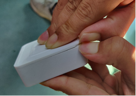
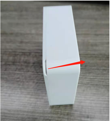
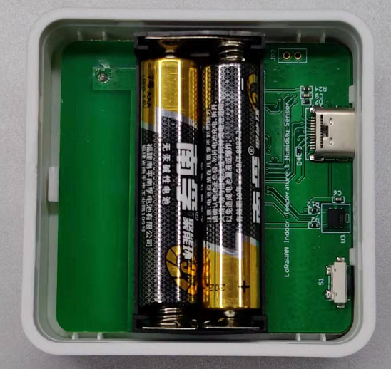
1. Open enclosure from below position.
2. Insert 2 x AAA LR03 batteries and the node is activated.

3. Under the above conditions, users can also reactivate the node by long pressing the ACT button.
User can check LED Status to know the working state of PB01.
2.3 Example to join LoRaWAN network
This section shows an example for how to join the TheThingsNetwork LoRaWAN IoT server. Usages with other LoRaWAN IoT servers are of similar procedure.
Assume the DLOS8 is already set to connect to TTN V3 network . We need to add the PB01 device in TTN V3 portal.
Step 1: Create a device in TTN V3 with the OTAA keys from PB01.
Each PB01 is shipped with a sticker with the default DEV EUI as below:

Enter these keys in the LoRaWAN Server portal. Below is TTN V3 screen shot:
Create application.
choose to create the device manually.
Add JoinEUI(AppEUI), DevEUI, AppKey.


Default mode OTAA
Step 2: Use ACT button to activate PB01 and it will auto join to the TTN V3 network. After join success, it will start to upload sensor data to TTN V3 and user can see in the panel.

2.4 Uplink Payload
Uplink payloads include two types: Valid Sensor Value and other status / control command.
- Valid Sensor Value: Use FPORT=2
- Other control command: Use FPORT other than 2.
2.4.1 Uplink FPORT=5, Device Status
Users can get the Device Status uplink through the downlink command:
Downlink: 0x2601
Uplink the device configures with FPORT=5.
| Size(bytes) | 1 | 2 | 1 | 1 | 2 |
|---|---|---|---|---|---|
| Value | Sensor Model | Firmware Version | Frequency Band | Sub-band | BAT |

Example Payload (FPort=5): ![]()
Sensor Model: For PB01, this value is 0x35.
Firmware Version: 0x0100, Means: v1.0.0 version.
Frequency Band:
*0x01: EU868
*0x02: US915
*0x03: IN865
*0x04: AU915
*0x05: KZ865
*0x06: RU864
*0x07: AS923
*0x08: AS923-1
*0x09: AS923-2
*0x0a: AS923-3
Sub-Band: value 0x00 ~ 0x08(only for CN470, AU915,US915. Others are0x00)
BAT: shows the battery voltage for PB01.
Ex1: 0x0C DE = 3294mV
2.4.2 Uplink FPORT=2, Real time sensor value
PB01 will send this uplink after Device Status uplink once join LoRaWAN network successfully. And it will periodically send this uplink. Default interval is 20 minutes and can be changed.
Uplink uses FPORT=2 and every 20 minutes send one uplink by default.
Size(bytes) | 2 | 1 | 1 | 2 | 2 |
|---|---|---|---|---|---|
Value | Battery | Sound_ACK &Sound_key | Alarm | Temperature | Humidity |
Example in TTN.

Example Payload (FPort=2): 0C EA 03 01 01 11 02 A8
Battery:
Check the battery voltage.
- Ex1: 0x0CEA = 3306mV
- Ex2: 0x0D08 = 3336mV
Sound_ACK & Sound_key:
Key sound and ACK sound are enabled by default.
- Example1: 0x03
Sound_ACK: (03>>1) & 0x01=1, OPEN.
Sound_key: 03 & 0x01=1, OPEN.
- Example2: 0x01
Sound_ACK: (01>>1) & 0x01=0, CLOSE.
Sound_key: 01 & 0x01=1, OPEN.
Alarm:
Key alarm.
- Ex1: 0x01 & 0x01=1, TRUE.
- Ex2: 0x00 & 0x01=0, FALSE.
Temperature:
- Example1: 0x0111/10=27.3℃
- Example2: (0xFF0D-65536)/10=-24.3℃
If payload is: FF0D : (FF0D & 8000 == 1) , temp = (FF0D - 65536)/100 =-24.3℃
(FF0D & 8000:Judge whether the highest bit is 1, when the highest bit is 1, it is negative)
Humidity:
- Humidity: 0x02A8/10=68.0%
2.4.3 Uplink FPORT=3, Datalog sensor value
PB01 stores sensor value and user can retrieve these history value via downlink command. The Datalog sensor value are sent via FPORT=3.

- Each data entry is 11 bytes, to save airtime and battery, PB01 will send max bytes according to the current DR and Frequency bands.
For example, in US915 band, the max payload for different DR is:
- DR0: max is 11 bytes so one entry of data
- DR1: max is 53 bytes so devices will upload 4 entries of data (total 44 bytes)
- DR2: total payload includes 11 entries of data
- DR3: total payload includes 22 entries of data.
Notice: PB01 will save 178 set of history data, If device doesn't have any data in the polling time. Device will uplink 11 bytes of 0.
See more info about the Datalog feature.
2.4.4 Decoder in TTN V3
In LoRaWAN protocol, the uplink payload is HEX format, user need to add a payload formatter/decoder in LoRaWAN Server to get human friendly string.
In TTN , add formatter as below:

Please check the decoder from this link: https://github.com/dragino/dragino-end-node-decoder
2.5 Show data on Datacake
Datacake IoT platform provides a human friendly interface to show the sensor data in charts, once we have sensor data in TTN V3, we can use Datacake to connect to TTN V3 and see the data in Datacake. Below are the steps:
Step 1: Be sure that your device is programmed and properly connected to the LoRaWAN network.
Step 2: Configure your Application to forward data to Datacake you will need to add integration. Go to TTN V3 Console --> Applications --> Integrations --> Add Integrations.
1. Add Datacake:
2. Select default key as Access Key:
3. In Datacake console (https://datacake.co/) , add PB01:
Please refer to the figure below.

Log in to DATACAKE, copy the API under the account.


Copy and paste the TTN decoder here and save.

Visual widgets please read the DATACAKE documentation.
2.6 Datalog Feature
When user want to retrieve sensor value, he can send a poll command from the IoT platform to ask sensor to send value in the required time slot.
2.6.1 Unix TimeStamp
Unix TimeStamp shows the sampling time of uplink payload. format base on

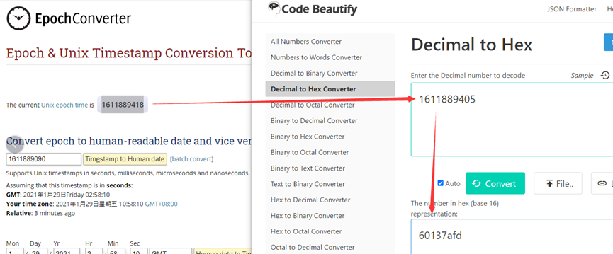
User can get this time from link: https://www.epochconverter.com/ :
For example: if the Unix Timestamp we got is hex 0x60137afd, we can convert it to Decimal: 1611889405. and then convert to the time: 2021 – Jan -- 29 Friday 03:03:25 (GMT)
2.6.2 Poll sensor value
User can poll sensor value based on timestamps from the server. Below is the downlink command.
Timestamp start and Timestamp end use Unix TimeStamp format as mentioned above. Devices will reply with all data log during this time period, use the uplink interval.
For example, downlink command 
Is to check 2020/12/1 07:40:00 to 2020/12/1 08:40:00's data
Uplink Internal =5s,means PB01 will send one packet every 5s. range 5~255s.
2.6.3 Datalog Uplink payload
See Uplink FPORT=3, Datalog sensor value
2.7 Button
- ACT button
Long press this button PB01 will reset and join network again.

- Alarm button
Press the button PB01 will immediately uplink data, and alarm is "TRUE".

2.8 LED Indicator
The PB01 has a triple color LED which for easy showing different stage.
Hold the ACT green light to rest, then the green flashing node restarts, the blue flashing once upon request for network access, and the green constant light for 5 seconds after successful network access
In a normal working state:
- When the node is restarted, hold the ACT GREEN lights up , then the GREEN flashing node restarts.The BLUE flashing once upon request for network access, and the GREEN constant light for 5 seconds after successful network access.
- During OTAA Join:
- For each Join Request uplink: the GREEN LED will blink once.
- Once Join Successful: the GREEN LED will be solid on for 5 seconds.
- After joined, for each uplink, the BLUE LED or GREEN LED will blink once.
- Press the alarm button,The RED flashes until the node receives the ACK from the platform and the BLUE light stays 5s.
2.9 Buzzer
The PB01 has button sound and ACK sound and users can turn on or off both sounds by using AT+SOUND.
- Button sound is the music produced by the node after the alarm button is pressed.
Users can use AT+OPTION to set different button sounds.
- ACK sound is the notification tone that the node receives ACK.
3. Configure PB01 via AT command or LoRaWAN downlink
Users can configure PB01 via AT Command or LoRaWAN Downlink.
- AT Command Connection: See FAQ.
- LoRaWAN Downlink instruction for different platforms: IoT LoRaWAN Server
There are two kinds of commands to configure PB01, they are:
- General Commands:
These commands are to configure:
- General system settings like: uplink interval.
- LoRaWAN protocol & radio-related commands.
They are the same for all Dragino Devices which supports DLWS-005 LoRaWAN Stack(Note**). These commands can be found on the wiki: End Device Downlink Command
- Commands special design for PB01
These commands are only valid for PB01, as below:
3.1 Downlink Command Set
| Command Example | Function | Response | Downlink |
|---|---|---|---|
| AT+TDC=? |
View current TDC time | 1200000 | Default 1200000(ms) |
| AT+TDC=300000 | Set TDC time | OK | 0X0100012C: 300(seconds)
|
| ATZ | Reset node | 0x04FF | |
| AT+FDR | Restore factory settings | 0X04FE | |
| AT+CFM=? | View the current confirmation mode status | 0,7,0 OK | Default 0,7,0 |
| AT+CFM=1,7,1 | Confirmed uplink mode, the maximum number of retries is seven, and uplink fcnt increase by 1 for each retry | OK | 05010701 05: fixed command 01:confirmed uplink 07: retry 7 times 01: fcnt count plus 1 |
| AT+NJM=? | Check the current network connection method | 1 | Default 1 |
| AT+NJM=0 | Change the network connection method to ABP | Attention:Take effect after ATZ | 0X2000: ABP |
| AT+RPL=? | View current RPL settings | 0 | Default 0 |
| AT+RPL=1 | set RPL=1 | OK | 0x2101: |
| AT+ADR=? | View current ADR status | 1 | Default 0 |
| AT+ADR=0 | Set the ADR state to off | OK | 0x2200: close |
| AT+DR=? | View the current DR settings | OK | |
| AT+DR=1 | set DR to 1 | OK | 0X22000101: |
| AT+TXP=? | View the current TXP | OK | |
| AT+TXP=1 | set TXP to 1 | OK | 0X22000101: |
| AT+RJTDC=10 | Set RJTDC time interval | OK | 0X26000A: |
____________________________ Retrieve stored data for a specified period of time
| 0X3161DE7C7061DE8A800A: | ||
| AT+DDETECT=? | View the current DDETECT setting status and time | 1,1440,2880 | Default 1,1440,2880(min) |
| AT+DDETECT= 1,1440,2880 | Set DDETECT setting status and time | OK | 0X320005A0: close |
3.2 Set Password
Feature: Set device password, max 9 digits.
AT Command: AT+PWORD
| Command Example | Function | Response |
| AT+PWORD=? | Show password | 123456 |
| AT+PWORD=999999 | Set password | OK |
Downlink Command:
No downlink command for this feature.
3.3 Set button sound and ACK sound
Feature: Turn on/off button sound and ACK alarm.
AT Command: AT+SOUND
| Command Example | Function | Response |
AT+SOUND=? | Get the current status of button sound and ACK sound | 1,1 |
AT+SOUND=0,1 | Turn off the button sound and turn on ACK sound | OK |
Downlink Command: 0xA1
Format: Command Code (0xA1) followed by 2 bytes mode value.
The first byte after 0XA1 sets the button sound, and the second byte after 0XA1 sets the ACK sound. (0: off, 1: on)
- Example: Downlink Payload: A10001 // Set AT+SOUND=0,1 Turn off the button sound and turn on ACK sound.
3.4 Set buzzer music type(0~4)
Feature: Set different alarm key response sounds.There are five different types of button music.
AT Command: AT+OPTION
| Command Example | Function | Response |
AT+OPTION=? | Get the buzzer music type | 3 OK |
| AT+OPTION=1 | Set the buzzer music to type 1 | OK |
Downlink Command: 0xA3
Format: Command Code (0xA3) followed by 1 byte mode value.
- Example: Downlink Payload: A300 // Set AT+OPTION=0 Set the buzzer music to type 0.
3.5 Set button sound time
Feature: Set the holding time for pressing the alarm button to avoid miscontact. Values range from 0 ~1000ms.
AT Command: AT+STIME
| Command Example | Function | Response |
AT+STIME=? | Get the button sound time | 0 |
AT+STIME=1000 | Set the button sound time to 1000ms | OK |
Downlink Command: 0xA2
Format: Command Code (0xA2) followed by 2 bytes mode value.
- Example: Downlink Payload: A203E8 // Set AT+STIME=1000
Explain: Hold the alarm button for 10 seconds before the node will send the alarm packet.
4. Battery & How to replace
4.1 Battery Type and replace
PB01 uses 2 x AAA LR03(1.5v) batteries. If the batteries running low (shows 2.1v in the platform). Users can buy generic AAA battery and replace it.
Note:
1. The PB01 doesn't have any screw, users can use nail to open it by the middle.
2. Make sure the direction is correct when install the AAA batteries.
4.2 Power Consumption Analyze
Dragino battery powered product are all runs in Low Power mode. We have an update battery calculator which base on the measurement of the real device. User can use this calculator to check the battery life and calculate the battery life if want to use different transmit interval.
Instruction to use as below:
Step 1: Downlink the up-to-date DRAGINO_Battery_Life_Prediction_Table.xlsx from:
Step 2: Open it and choose
- Product Model
- Uplink Interval
- Working Mode
And the Life expectation in difference case will be shown on the right.

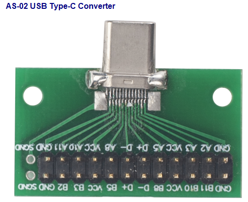
5. Accessories
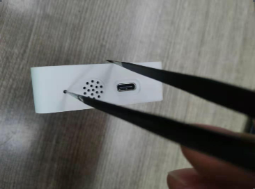
Program Converter (AS-02)
AS-02 is an optional accessory, it is USB Type-C converter. AS-02 provide below feature:
- Access AT console of PB01 when used with USB-TTL adapter. See this link.
6. FAQ
6.1 How to use AT Command to configure PB01
PB01 supports AT Command set. Users can use a USB to TTL adapter plus the Program Cable to connect to PB01 for using AT command, as below.

Connection:
- USB to TTL GND <--> Program Converter GND pin
- USB to TTL RXD <--> Program Converter D+ pin
- USB to TTL TXD <--> Program Converter A11 pin
In PC, User needs to set serial tool(such as putty, SecureCRT) baud rate to 9600 to access to access serial console for PB01. The AT commands are disable by default and need to enter password (default:123456) to active it. Timeout to input AT Command is 5 min, after 5-minute, user need to input password again.
Input password and ATZ to activate PB01, as shown below:

6.2 AT Command and Downlink
Sending ATZ will reboot the node
Sending AT+FDR will restore the node to factory settings
Get the node's AT command setting by sending AT+CFG
Example:
AT+DEUI=FA 23 45 55 55 55 55 51
AT+APPEUI=FF AA 23 45 42 42 41 11
AT+APPKEY=AC D7 35 81 63 3C B6 05 F5 69 44 99 C1 12 BA 95
AT+DADDR=FFFFFFFF
AT+APPSKEY=FF FF FF FF FF FF FF FF FF FF FF FF FF FF FF FF
AT+NWKSKEY=FF FF FF FF FF FF FF FF FF FF FF FF FF FF FF FF
AT+ADR=1
AT+TXP=7
AT+DR=5
AT+DCS=0
AT+PNM=1
AT+RX2FQ=869525000
AT+RX2DR=0
AT+RX1DL=5000
AT+RX2DL=6000
AT+JN1DL=5000
AT+JN2DL=6000
AT+NJM=1
AT+NWKID=00 00 00 13
AT+FCU=61
AT+FCD=11
AT+CLASS=A
AT+NJS=1
AT+RECVB=0:
AT+RECV=
AT+VER=EU868 v1.0.0
AT+CFM=0,7,0
AT+SNR=0
AT+RSSI=0
AT+TDC=1200000
AT+PORT=2
AT+PWORD=123456
AT+CHS=0
AT+RX1WTO=24
AT+RX2WTO=6
AT+DECRYPT=0
AT+RJTDC=20
AT+RPL=0
AT+TIMESTAMP=systime= 2024/5/11 01:10:58 (1715389858)
AT+LEAPSEC=18
AT+SYNCMOD=1
AT+SYNCTDC=10
AT+SLEEP=0
AT+ATDC=1
AT+UUID=003C0C53013259E0
AT+DDETECT=1,1440,2880
AT+SETMAXNBTRANS=1,0
AT+DISFCNTCHECK=0
AT+DISMACANS=0
AT+PNACKMD=0
AT+SOUND=0,0
AT+STIME=0
AT+OPTION=3
Example:

6.3 How to upgrade the firmware?
PB01 requires a program converter to upload images to PB01, which is used to upload image to PB01 for:
- Support new features
- For bug fix
- Change LoRaWAN bands.
User can check this link for the detail of operation of firmware upgrade: Firmware Upgrade Instruction
6.4 How to change the LoRa Frequency Bands/Region?
User can follow the introduction for how to upgrade image. When download the images, choose the required image file for download.
6.5 Why i see different working temperature for the device?
The working temperature range of device depends on the battery user choose.
- Normal AAA Battery can support -10 ~ 50°C working range.
- Special AAA battery can support -40 ~ 60 °C working range. For example: Energizer L92
7. Order Info
7.1 Main Device
Part Number: PB01-LW-XX (white button) / PB01-LR-XX(Red Button)
XX : The default frequency band
- AS923: LoRaWAN AS923 band
- AU915: LoRaWAN AU915 band
- EU433: LoRaWAN EU433 band
- EU868: LoRaWAN EU868 band
- KR920: LoRaWAN KR920 band
- US915: LoRaWAN US915 band
- IN865: LoRaWAN IN865 band
- CN470: LoRaWAN CN470 band
7. Packing Info
Package Includes:
- PB01 LoRaWAN Push Button x 1
8. Support
- Support is provided Monday to Friday, from 09:00 to 18:00 GMT+8. Due to different timezones we cannot offer live support. However, your questions will be answered as soon as possible in the before-mentioned schedule.
- Provide as much information as possible regarding your enquiry (product models, accurately describe your problem and steps to replicate it etc) and send a mail to support@dragino.com.
9. Reference material
10. FCC Warning
This device complies with part 15 of the FCC Rules.Operation is subject to the following two conditions:
(1) This device may not cause harmful interference;
(2) this device must accept any interference received,including interference that may cause undesired operation.